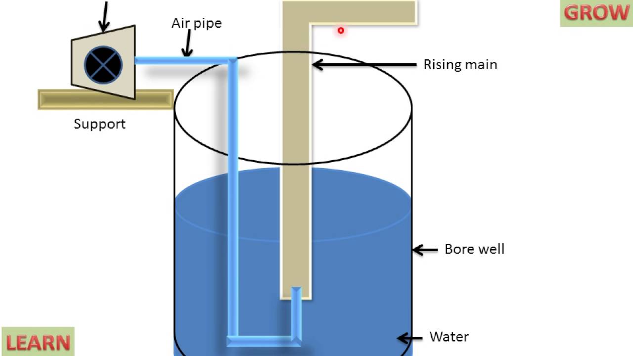
Schematic of the air-lift pump system Physics 1 for kma [diagram] wiring diagram for lift pump
Figure 6.1 is a schematic diagram of a lift pump | Chegg.com
Lift-pump hosted at imgbb — imgbb
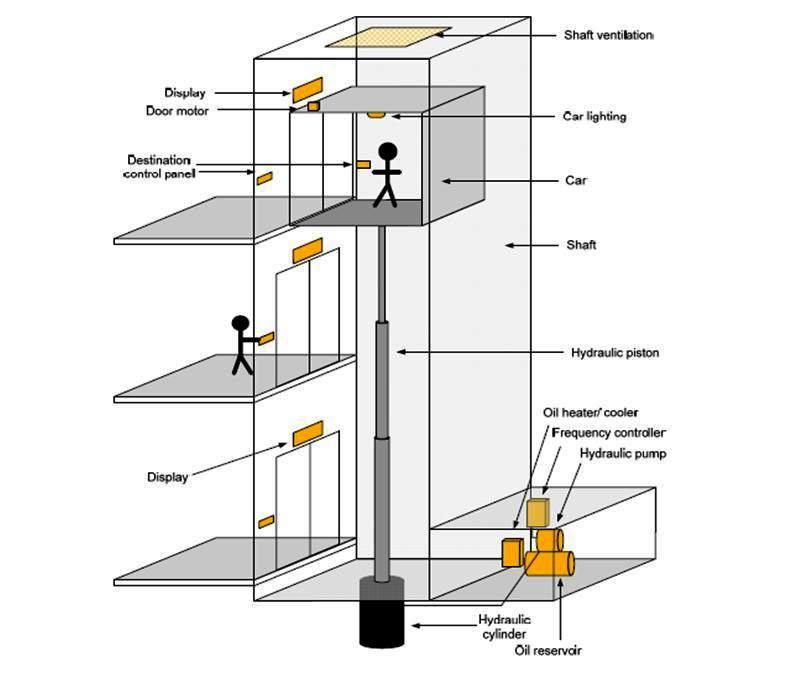
Elevator anatomy for lawyers
Diagram of a lift-and-force pump driven by a linear motor withSchematic diagram of the main body of the airlift pump. How does artificial lift work?Air lift pump.
Pump lifter high water diagram solar directory service coast regional manufacturers network north humboldt redwood rural actionHydraulic elevators are lift systems that use a hydraulic piston to Parts of air lift pumpPump lift piston shows figure explain why when.

Figure 6.1 is a schematic diagram of a lift pump
Hydraulics pump, power equation – hydraulic schematic troubleshootingResidential sewage lift station design How does a lift station work?Sewage lift station pump system.
Lable the diagram of hydraulic lift[diagram] wiring diagram for lift pump Air lift pumpLift pump online physics.

Combined science,,, how a lift pump operate (0712769887)
Lift shaft ventilationHumboldt solar water pump/ high lifter pump service » north coast Water lifting devicesFigure 14 shows a lift pump..
Figure 6.1 is a schematic diagram of a lift pumpLift pump level control diagram Elevators elevator ventilation knowhow piston duct rise pushes airway fluidElevator hydraulic traction schematic anatomy systems structure components pdf article.

Parts of air lift pump
Pump equation lift troubleshooting hydraulics power uncategorized schematic hydraulicSolved the pump shown in the figure below is used to lift Grinder pump sewage lift stations from triple d pumpPin on air/water lift pump.
Sewage ejector pump cost .